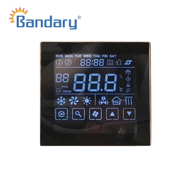
1, Power supply:8-12VDC
2, Self consumption:<0.1w
3, Protection:IP20
4, Working temperature :0-50DegC
5, Ambient humidity : 5-93%RH
6, Keypad: capacitor touch screen keypad
7, Enclosure material: Fire-proof ABS
8, Hope pitch :standard wiring case 60mm


|
Sensor Input Data- BAC01
|
|||||||||
|
Item
|
port
|
Name
|
Vlaue of resistance
|
Description
|
|||||
|
1
|
TH1
|
Toe:outdoor ambient temperature
|
10K
|
temperature range limited and defrost judgement
|
|||||
|
2
|
TH2
|
Tos: total outlet water temperature
|
10K
|
only for the outdoor connection ,it can be used to adjust the load of the unit
|
|||||
|
3
|
TH3
|
Tr:total return water temperature
|
10K
|
only for the outdoor connection ,it can be used to adjust the load of the unit
|
|||||
|
4
|
TH4
|
To: outlet water temperature
|
10K
|
Frost protection
|
|||||
|
5
|
TH5
|
Tcs1:1# suction temperature
|
10K
|
superheat adjustment
|
|||||
|
6
|
TH6
|
Tdis1:1# discharge temperature
|
100K
|
discharge superheat protection
|
|||||
|
7
|
TH7
|
Tevi1:1# EVI inlet temperature
|
10K
|
EVI superheat adjustment
|
|||||
|
8
|
TH8
|
Tevo1:1# EVI outlet temperature
|
10K
|
EVI superheat adjustment
|
|||||
|
9
|
TH9
|
Tcs2: 2# suction temperature
|
10K
|
superheat adjustment
|
|||||
|
10
|
TH10
|
Tdis2:2# discharge temperature
|
100K
|
discharge superheat protection
|
|||||
|
11
|
TH11
|
Tevi2:2# EVI inlet temperature
|
10K
|
EVI superheat adjustment
|
|||||
|
12
|
TH12
|
Tevo2:2# EVIoutlet temperature
|
10K
|
EVI superheat adjustment
|
|||||
|
Input / Output Ports Data- BAC01
|
|||||||
|
Item
|
Port
|
Description
|
Remark
|
||||
|
1
|
CN1
|
RS485 communication port is for slave
|
when communication with BMS system (Modbus protocol ),if this unit is treated as slave ,the communication port is CN10 to Master
|
||||
|
2
|
CN2
|
SLM wired controller port
|
review outdoor unit variables and parameter settings
|
||||
|
3
|
CN3
|
compressor driver communication port
|
communication with compressor driver board
|
||||
|
4
|
CN5
|
Programming port
|
it is used for upgraded .
|
||||
|
5
|
CN6
|
EXV 1 port
|
1# the master EXV
|
||||
|
6
|
CN7
|
EXV 2 port
|
2# the master EXV
|
||||
|
7
|
CN8
|
EXV 3 port
|
1# EVI
|
||||
|
8
|
CN9
|
EXV 4 port
|
2# EVI
|
||||
|
9
|
CN10
|
Master communication port
|
when communication with BMS system (Modbus protocol ),if this unit is treated as master ,the communication port is CN1 to slave.
|
||||
|
10
|
CN11
|
High/low pressure sensor port
|
2# high pressure (Pd2)and low pressure (Ps2)sensor
|
||||
|
11
|
Ps1
|
low pressure sensor port
|
1# low pressure sensor
|
||||
|
12
|
Pd1
|
high pressure sensor port
|
1# high pressure sensor
|
||||
|
13
|
CN12
|
power input
|
220VAC
|
||||
|
14
|
CN13
|
neutral line
|
neutral line is for group 1 output
|
||||
|
15
|
CN14
|
Group1 relays output
|
O11,O12,O13,O14( 4-way output )
|
||||
|
16
|
CN15
|
neutral line
|
neutral line is for group 2 output
|
||||
|
17
|
CN16
|
Group2 relays output
|
O21,O22,O23,O24( 4-way output)
|
||||
|
18
|
CN17
|
neutral line
|
neutral line is for group 3 output
|
||||
|
19
|
CN18
|
Group 3 relays output
|
O31,O32,O33,O34 (4-way output)
|
||||
|
20
|
CN19
|
neutral line
|
neutral line is for group 4 toutput
|
||||
|
21
|
CN20
|
Group 4 relays output
|
O41,O42,O43 (3-way output)
|
||||
|
22
|
CN21
|
Dry contact output
|
DO1,DO2 (2-way output ,share the same COM)
|
||||
